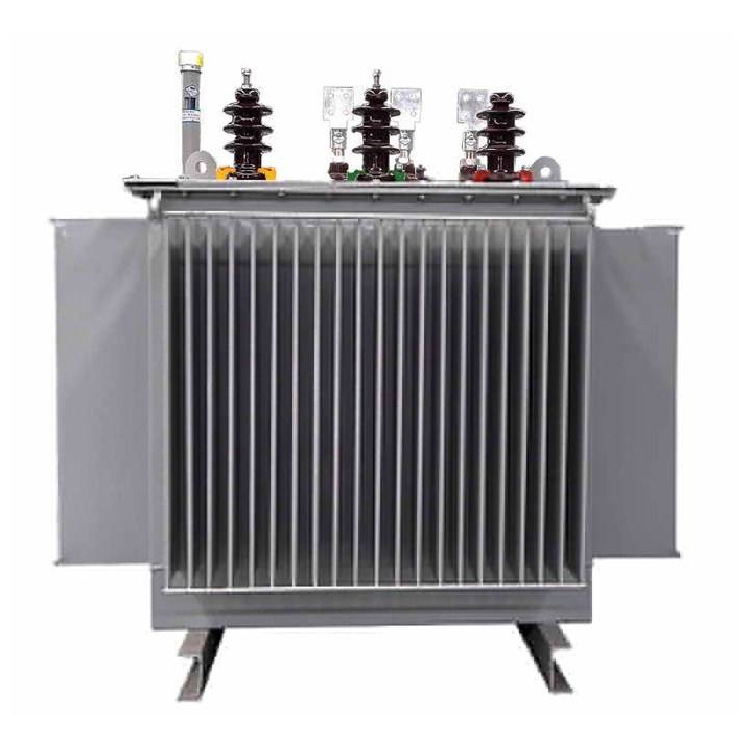
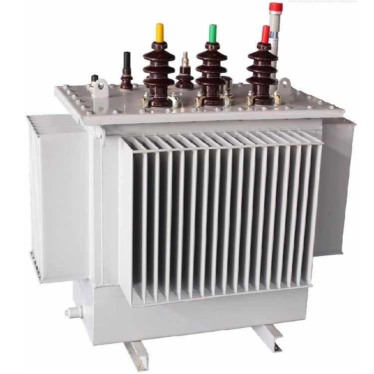
Armophous Alloy Distribution Transformer
keyword:
Classification:
Products Details
| S(B)H15 Armophous Alloy Distribution Transformer | |||||||||||
| Rated Capacity (kVA) |
Rated primary voltage(kV) | H.V. Tap range (%) |
Rated Secondary voltage(kV0) | Connection symbol | No-load Loss (kW) |
On-load Loss (kW) |
No-load current (%) |
Short circuit impedance | Weight (KG) |
L*W*H (mm) |
Gauge (mm*mm) |
| 30 | 6 6.3 10 10.5 11 |
±5 ±2*2.5 |
0.4 | Dyn 11 Yyn0 |
33 | 630/600 | 1.50 | 4.0 | 390 | 875*705*815 | 550*550 |
| 50 | 43 | 910/870 | 1.20 | 450 | 1025*745*845 | 550*550 | |||||
| 63 | 50 | 1090/1040 | 1.10 | 610 | 1050*760*885 | 550*550 | |||||
| 80 | 60 | 1310/1250 | 1.00 | 655 | 1075*870*890 | 550*550 | |||||
| 100 | 75 | 1580/1500 | 0.90 | 685 | 1100*880*900 | 550*550 | |||||
| 125 | 85 | 1890/1800 | 0.80 | 755 | 1175*915*910 | 550*550 | |||||
| 160 | 100 | 2310/2200 | 0.60 | 805 | 1200*935*920 | 660*660 | |||||
| 200 | 120 | 2730/2600 | 0.60 | 895 | 1255*950*925 | 660*660 | |||||
| 250 | 140 | 3200/3050 | 0.60 | 1315 | 1350*955*935 | 660*660 | |||||
| 315 | 170 | 3830/3650 | 0.50 | 1445 | 1480*995*970 | 660*660 | |||||
| 400 | 200 | 4520/4300 | 0.50 | 1500 | 1580*1140*975 | 820*820 | |||||
| 500 | 240 | 5410/5150 | 0.50 | 1720 | 1660*1170*980 | 820*820 | |||||
| 630 | 320 | 6200 | 0.30 | 4.5 | 2100 | 1750*1195*1080 | 820*820 | ||||
| 800 | 380 | 7500 | 0.30 | 2720 | 1860*1255*1135 | 820*1070 | |||||
| 1000 | 450 | 10300 | 0.30 | 3410 | 1950*1355*1250 | 820*1070 | |||||
| 1250 | 530 | 12000 | 0.20 | 4230 | 2120*1435*1310 | 820*1070 | |||||
| 1600 | 630 | 14500 | 0.20 | 5420 | 2350*1550*1430 | 820*1070 | |||||
| Note :1. For transformers with rated capacities of 500kVA and below, the load loss values above the diagonal line in the table are applicable to Dyn11 coupling group, and the load loss values below the diagonal line are applicable to Yyn0 coupling group; 2. According to user needs, can provide other high-voltage tap range of three-phase transformer 3. The dimensions in the table are for reference only, and the final shape drawing confirmed with the user shall prevail. |
|||||||||||
| S(B)H21 Armophous Alloy Distribution Transformer | |||||||||||
| Rated Capacity (kVA) |
Rated primary voltage(kV) | H.V. Tap range (%) |
Rated Secondary voltage(kV0) | Connection symbol | No-load Loss (kW) |
On-load Loss (kW) |
No-load current (%) |
Short circuit impedance | Weight (KG) |
L*W*H (mm) |
Gauge (mm*mm) |
| 30 | 6 6.3 10 10.5 11 |
±5 ±2*2.5 |
0.4 | Dyn 11/ Yyn0 |
33 | 535/510 | 1.50 | 4.0 | |||
| 50 | 43 | 780/745 | 1.20 | ||||||||
| 63 | 50 | 930/890 | 1.10 | ||||||||
| 80 | 60 | 1120/1070 | 1.00 | ||||||||
| 100 | 75 | 1350/1285 | 0.90 | ||||||||
| 125 | 85 | 1615/1540 | 0.80 | ||||||||
| 160 | 100 | 1975/1880 | 0.60 | ||||||||
| 200 | 120 | 2330/2225 | 0.60 | ||||||||
| 250 | 140 | 2735/2610 | 0.60 | ||||||||
| 315 | 170 | 3275/3120 | 0.50 | ||||||||
| 400 | 200 | 3865/3675 | 0.50 | ||||||||
| 500 | 240 | 4625/4400 | 0.50 | ||||||||
| 630 | Dyn 11/ Yyn0 |
320 | 5300 | 0.30 | 4.5 | ||||||
| 800 | 380 | 6415 | 0.30 | ||||||||
| 1000 | 450 | 8800 | 0.30 | ||||||||
| 1250 | 530 | 10260 | 0.20 | ||||||||
| 1600 | 630 | 12400 | 0.20 | ||||||||
| 2000 | 710 | 14800 | 0.20 | 5 | |||||||
| 2500 | 860 | 16300 | 0.20 | ||||||||
| Note: 1. When the core is three-phase three-column, Yyn0 coupling group can also be used according to the need. 2. For transformers with rated capacities of 500kVA and below, the load loss values above the diagonal line in the table are applicable to Dyn11 coupling group, and the load loss values below the diagonal line are applicable to Yyn0 coupling group. 3· If the user needs, other loss values can also be selected. 4. According to user needs, can provide other high-voltage tap range of three-phase transformer. |
|||||||||||
| S(B)H25 Armophous Alloy Distribution Transformer | |||||||||||
| Rated Capacity (kVA) |
Rated primary voltage(kV) | H.V. Tap range (%) |
Rated Secondary voltage(kV0) | Connection symbol | No-load Loss (kW) |
On-load Loss (kW) |
No-load current (%) |
Short circuit impedance | Weight (KG) |
L*W*H (mm) |
Gauge (mm*mm) |
| 30 | 6 6.3 10 10.5 11 |
±5 ±2*2.5 |
0.4 | Dyn 11/ Yyn0 |
25 | 510/480 | 1.50 | 4.0 | |||
| 50 | 35 | 735/700 | 1.20 | ||||||||
| 63 | 40 | 880/840 | 1.10 | ||||||||
| 80 | 50 | 1060/1010 | 1.00 | ||||||||
| 100 | 60 | 1270/1215 | 0.90 | ||||||||
| 125 | 70 | 1530/1450 | 0.80 | ||||||||
| 160 | 80 | 1870/1780 | 0.60 | ||||||||
| 200 | 95 | 2210/2100 | 0.60 | ||||||||
| 250 | 110 | 2590/2470 | 0.60 | ||||||||
| 315 | 135 | 3100/2950 | 0.50 | ||||||||
| 400 | 160 | 3660/3480 | 0.50 | ||||||||
| 500 | 190 | 4380/4170 | 0.50 | ||||||||
| 630 | Dyn 11/ Yyn0 |
250 | 5020 | 0.30 | 4.5 | ||||||
| 800 | 300 | 6075 | 0.30 | ||||||||
| 1000 | 360 | 8340 | 0.30 | ||||||||
| 1250 | 425 | 9720 | 0.20 | ||||||||
| 1600 | 500 | 11745 | 0.20 | ||||||||
| 2000 | 550 | 14000 | 0.20 | 5 | |||||||
| 2500 | 670 | 15450 | 0.20 | ||||||||
| Note: 1. When the core is three-phase three-column, Yyn0 coupling group can also be used according to the need. 2. For transformers with rated capacities of 500kVA and below, the load loss values above the diagonal line in the table are applicable to Dyn11 coupling group, and the load loss values below the diagonal line are applicable to Yyn0 coupling group. 3· If the user needs, other loss values can also be selected. 4. According to user needs, can provide other high-voltage tap range of three-phase transformer. |
|||||||||||
Product Description
The amorphous alloy core is made by winding amorphous alloy strip. Amorphous alloy is a new type of strip. It is an amorphous material formed by the rapid solidiization process of the alloy composed of 80%Fe and 20%Si and B metal elements, which has extremely superior physical and electromagnetic properties. It has the advantages of high saturation magnetic induction, high resistivity, low coercivity, low loss and low excitation power. Amorphous alloy core transformer is a new type of energy saving transformer, and it is an ideal product for the renewal of distribution network.
1. Oxygen-free copper wire is used in high voltage coil, and copper foil coil is used in low voltage coil to increase the ability of transformer to withstand short circuit.
2. Vacuum drying and vacuum oil filling process are used to completely discharge the bubbles and moisture in the coil to ensure the stability of insulation performance.
3. The box adopts fully sealed structure, which can make the transformer isolated from the atmosphere, prevent and slow down the deterioration of oil and insulation damp. Extended service life, maintenance free.
4. The transformer coupling group adopts Dyn11 to avoid the influence of high-order harmonics on the grid and improve the quality of power supply.
Product Features
1. Low noise
The core is distributed lap TYPE coil core structure, using low noise high quality amorphous and gold strip, applying advanced noise reduction structure and technology, so that the noise can meet the requirements of the noise sensitive area.
2. Long life
The oil tank adopts a fully sealed structure, and the transformer oil does not contact the outside world. The oil expansion depends on the elasticity of the corrugated plate to compensate, so as to delay the aging of the insulation material inside the body.
3. Low loss
Compared with silicon steel core transformer, amorphous alloy core transformer has superior no-load performance. The no-load loss is 65% lower than that of S11 type silicon steel core transformer, and 50% lower than that of S13 type silicon steel core transformer. It is an energy-saving distribution transformer that is currently widely used.
Related Products
undefined
Inquiry Now
Welcome to leave your information to get contact with us!
Tel
Add
Jikai Electric Power Technology Industrial Park,Baoding City, Hebei Province, China.
Share our website
Copyright © 2022 Baoding Jikai Power Equipment Co., Ltd. All Rights Reserved.


 Language


